- 7,724
- 10,886
- 113
- Location
- Papalote, TX
I will resume the search when the weather and my health improve, I have the horrible flue that is going around, it seems to last forever.Yes sir, I would still be interested in the remanufactured FAV dash.
Steel Soldiers now has a few new forums, read more about it at: New Munitions Forums!

I will resume the search when the weather and my health improve, I have the horrible flue that is going around, it seems to last forever.Yes sir, I would still be interested in the remanufactured FAV dash.
Is that a Short/Quick Shifter block i see?No, the center pod is part of the dash and I have no interest in cannibalizing it. I restored the old dash, the "spare" new dash is blank
YesIs that a Short/Quick Shifter block i see?
(No I'm not a rivet nazi, matter of fact I'm messing with Duck Boards for 0014, primarily to keep my heel positioned at the throttle pedal to spare my back pain. I was going to have half piece of tube welded to a flat plate to fit between throttle pedal base and the chassis)
I will check it out, probably cannot help with overall length.#10-32 Morse 3C? Throttle Cable: Do you happen to recall the overall length? My mockup suggests 8ft.
Then I have the NEAL pedal, the hex standoff from pedal to the internal spring QR ball joint and front anchor clamp/shim sorted out.
But the carburetor end, does the throttle cable get anchored to the fan shroud?
Or does it just depend on the front anchored and length zip tied to the chassis?
Assume cable gets routed between fuel cell and radio shelf? Or under the fuel cell?
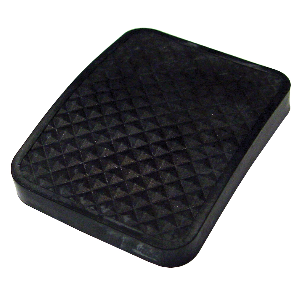
Btw, this black rubber clutch/brake pedal cover should fit your NEALs/CNC:I will check it out, probably cannot help with overall length.
 appletreeauto.com


For discussion sake, since one day I'll have to try to recreate the FAV beam if an original doesn't turn up, through your investigation into your primary sources and technical breakdown of the FAV beam, is it your professional opinion the FAV beams were manufactured by/for Chenowth from scratch, not cut/lengthened original VW link pin beams? It would be more efficient to make the beams from scratch, the jig fixturing being the most labor extensive portion of the operation. Mill out 2" OD 0.12: chrome-moly DOM for the 2 adjuster slots, clamp in the fixture, weld on the 2 vertical U channel spacers; weld on the adjuster channel stock guards; weld on the R&P mount; weld on the custom shock towers; ream the DOM ends for the roller bearing/bakelite bushings; drill/tap for grease zerks to retain the bakelite bushings.The front end on the FAV is a strange duck.
It was built by Chenowth, most oversize beams were built by Warrior.
When I first measured it I thought it was a 9 1/4" (stock beam tube width is 34 1/4" my beam tubes are close to 43 1/2", = 9 1/4") but measuring the grub screws center/center showed it to be a 9" over. (this IS the definitive measurement for beam front ends)


I found the dash, will get a couple pics to you tomorrowYes sir, I would still be interested in the remanufactured FAV dash.
Thank you, Sir!I found the dash, will get a couple pics to you tomorrow