• Steel Soldiers now has a few new forums, read more about it at: New Munitions Forums!

  • Microsoft MSN, Live, Hotmail, Outlook email users may not be receiving emails. We are working to resolve this issue. Please add support@steelsoldiers.com to your trusted contacts.

Protective Control Box (PCB) identification

HHSIII

New member
6
2
3
Location
Gales Ferry, CT
I have seen several posting stating that The 9xx series vehicle PCB can be used on a 8xx series vehicles but the 8xx PCB can't be used on the 9xx vehicle.
My problem has been that there is never any discussion on the identifying features of the two different boxes.
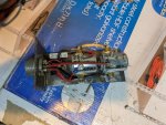
I.E. I have several PCB on the shelf. One has two 24063 style solenoids and no circuit board. Is this a 800 or a 900 box? Another unit has a 24063 style solenoid (markings SAS 4419) with a phenolic style solenoid as the front solenoid. This box also has a circuit board. Is this a 800 or a 900 box?
Any and all input is appreciated.
HHSIII
 

HHSIII

New member
6
2
3
Location
Gales Ferry, CT
Kendelrio- Thank you for the information. That is exactly what I was looking for. My unit is not in the "coffin" box but the layout and design appears to be the same as that pictured. I have rebuilt the unit: new solenoids, new resistors, some new diodes. Post rebuild, in truck testing was sat. I also have a 800 PCB box, (contains the circuit board) based on the information you provided. Currently testing it. All appears good at this point. We need to decide if we market it or strip it and turn it into a 900 box.
Again, thanks for the direction and advice. Take care and stay safe.
HHSIII
 

kendelrio

Well-known member
Steel Soldiers Supporter
2,991
9,899
113
Location
Alexandria, La
Kendelrio- Thank you for the information. That is exactly what I was looking for. My unit is not in the "coffin" box but the layout and design appears to be the same as that pictured. I have rebuilt the unit: new solenoids, new resistors, some new diodes. Post rebuild, in truck testing was sat. I also have a 800 PCB box, (contains the circuit board) based on the information you provided. Currently testing it. All appears good at this point. We need to decide if we market it or strip it and turn it into a 900 box.
Again, thanks for the direction and advice. Take care and stay safe.
HHSIII
No worries bud! Glad I could help!
 

HHSIII

New member
6
2
3
Location
Gales Ferry, CT
That is information you might find in the TM. Look in the parts TM for the UOC, Usable On Code.
Thank you. I just wish it was that easy. I have been studying Section 1-19 (Electrical System) of the TM 9-2320-272-10. I have found a lot of good information but not the answers to my questions. I.E. Box IDs, Circuit board, no circuit board, which vehicle uses which? etc.
I have completely rebuilt a non-circuit board box. New solenoids, resistors, diodes, and MOSFET. We have reinstalled it on the M939A2 5 ton truck and all seems to be working well. Posts I've seen state that the non-circuit board box is the 800 series box and it should will not work on a 900 series vehicles. So I remain confused. Pictures of the two attached. Last picture (xx970) is the rebuild.
Using Section 1-19 I have been trying to create a electrical (starter and control) section of a schematic. I'd like to create on of the PCB circuit board by reverse engineering, but for a mechanical guy that is stretching my ability. So, I am still looking for a schematic of the PCB circuit board and the electrical system in general. Are there any out there, Military provided or Owner/Enthusiast generated.
Final comment. I am beginning to believe that the PCB is really a small part and contributor to the system. I used to think it did more but am beginning to think otherwise. I am starting to see it as a safety item to prevent engagement of the starter while the vehicle is running, otherwise it is simply a system pass through box.
I am still very interested in what others think and have found.
Take care. HHSIII
 

Attachments

Last edited:

Jbulach

Well-known member
Steel Soldiers Supporter
2,781
2,477
113
Location
Sunman Indiana

Check out post #21 by @cwc and see if thats what you looking for? Lots of other good stuff spread throughout that thread as well.
 

HHSIII

New member
6
2
3
Location
Gales Ferry, CT
I am not an electrical guy myself. My background is mechanical and knuckle dragging.
That burned out item looks like a film capacitor to me. Those are also film capacitors up on the back side of the connector. If you are lucky the markings for the burned out capacitor is on the side that is not smoked. If the markings were on the side that got smoked I would look at those that are on the back of the connector and install that size in place of the burned out one. If you come up with numbers and need help in interpreting the numbers, sing out. The blue item looks like an electrolytic capacitor. Try to see or feel the top of that capacitor. If it is bulged out it should be replaced. If not it is probably good. The black torrid rings that the wires are wrapped around look like simple chokes or "mode chokes". They just act as filters to block HF noise and interference.
Bottom line, you replace the smoked film capacitor and you may be good to go. If you can't come up with numbers just install a unit that has some meat to it and try it. If it smokes, go higher. One of the Electrical Gurus might be able to give you the specs on one they think is good to use.
Good luck and take care, work safe/ cruise safe.
HHSIII
 
Top